[65호]스마트 차선 변경 시스템
2020 ICT 융합 프로젝트 공모전 장려상
스마트 차선 변경 시스템
글 | 영남대학교 양성은, 박유나, 지준영
1. 심사평
칩센 지원자께서는 ‘ADAS(Advanced Driver-Assistance Systems)’ 라는 용어나 시스템을 들어보셨을 수도 있을듯합니다. 최근 많은 차량에 운전, 주차, 안전을 위한 여러 가지 시스템이 적용되고 있고, 그 중 지원자가 구현하고자 한 작품은 ADAS 기능 중 BCW 기능에 해당할 것으로 보입니다. 보고서에도 작성되어 있듯이 실제로는 고려하기 힘든 많은 변수들이 있고 그러한 부분을 이미 진행된 기술의 학습을 통해서 개선이 가능할 것으로 보입니다. 시연 영상에서 실제 도로와 유사한 이미지로 화면이 보이는 것이 매우 흥미로웠습니다.
펌테크 현재 상용화되어 널리 사용되는 기술이지만 학생의 눈높이에 맞추어 전체적으로 꼼꼼하게 잘 기획되었고, 간결하게 잘 구성한 작품이라고 생각합니다. 제품 완성도 면에서 우수한 작품이라고 판단됩니다.
위드로봇 차량의 BSD 기능을 구현한 작품입니다. 카메라 캘리브레이션을 통해 초음파 센서 거리 값과 융합을 하면 더 좋은 결과를 얻을 수 있습니다.
2. 작품 개요
2.1. 구현 배경
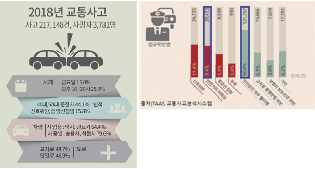
TAAS 교통사고분석시스템에 따르면, 2018년 교통사고는 21만 건이 넘는 사고와 3,781명의 사망자가 발생했으며 교통사고로 수년간 인명피해가 많이 발생하고 있다. 이러한 교통사고가 일어나는 경우는 신호 위반, 안전거리 미확보, 중앙선 침범, 과속, 안전운전 의무 불이행, 교차로 통행방법 위반, 보행자 보호의무 위반 등 여러 가지가 있다.
여기서 도로교통공단에서 제시한 안전운전(안전한 도로이용)수칙에는 안전거리 유지, 좌석 안전벨트의 착용, 진로 변경 등을 다루고 있다. 안전거리 유지 관련 기술은 고속도로 주행보조(HDA)로 고속도로와 자동차 전용도로 주행 시 앞차와의 거리를 유지하며 운전자가 설정한 속도로 곡선로에서도 차선을 유지하며 주행하도록 돕는 기술이 있다. 자동차 안전벨트 미착용 알림장치 뿐만 아니라 후진 주차/출차 시 후방 장애물 인식 및 제동을 돕는 후방 주차 충돌방지 보조(PCA)등을 탑재해 안전 편의성을 극대화하였다.
따라서 우리가 구현하고자 하는 기술은 차선 변경에 대한 교통사고를 일으키는 원인의 시발점을 봉쇄하는 동시에 이와 같은 스마트한 시대에 걸 맞는 기술을 접목 시킬 기술을 구현하는 것이다.
2.2. 스마트 차선 변경 시스템이란?
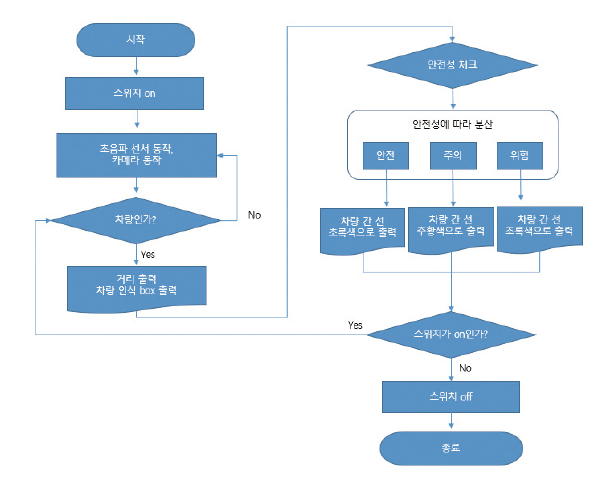
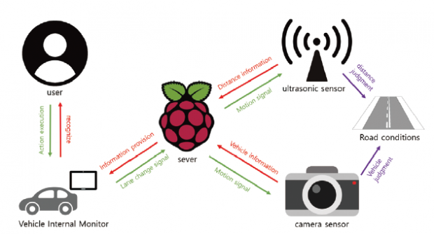
스마트 차선 변경 시스템은 운전자가 방향지시등을 키게 되면 변경하고자하는 차선의 운전자 차량 기준에서 가장 가까운 차량과의 거리를 실시간으로 측정하여 운전자의 차량 내 모니터를 이용해 시각적인 정보를 제공함으로써, 운전자가 보다 안전하고 편리하게 차선변경을 할 수 있도록 도움을 주는 시스템이다.
초음파 센서를 통해 거리를 측정하여 차선 변경 시 운전자에게 위험(빨강색) – 주의(주황색) – 안전(초록색) 세 단계로 나누어 시각화 함으로서 위험을 좀 더 쉽게 감지할 수 있게 돕는다.
2.3. 대상 및 기대효과
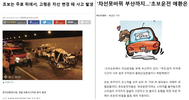
한국 교통 연구원, 경찰 교통사고자료 분석 결과에 따르면 차선을 변경 시 충돌사고를 많이 내는 것으로 나타났다. 그리고 차선 변경을 하지 못해 부산까지 갔다는 기사를 접할 수 있다. 이와 같이 해당 기술의 초점 대상은 운전에 미숙한 사람으로 해당 기술은 차선 변경에 대한 부담감을 줄이고 안전편의성을 극대화하는 역할을 한다.
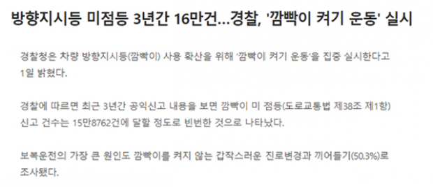
또 운전에 미숙한 사람뿐만 아니라 모든 운전자를 대상으로 확장 할 수 있다. 도로를 나가보면 상당히 많은 운전자들이 차선 변경 시 방향지시등을 켜지 않은 모습을 볼 수 있는데, 이유를 물어보면 대다수가 “귀찮아서”라는 대답을 한다. 운전자들이 대수롭지 않게 생각하여 잘 사용하지 않는 기능을 개선하여 보다 안전하게 운전할 수 있다는 장점을 살려 방향지시등을 사용하게끔 유도하는 효과도 기대해본다.
끝으로 차선 변경 시 일어나는 교통문제를 개선해 조금이라도 더 많은 운전자가 편리하고 안전한 도로 주행을 하길 바라는 기대를 해본다.
3. 작품 설명
3.1. 주요 동작 및 특징
3.1.1. 카메라 동작 및 특징
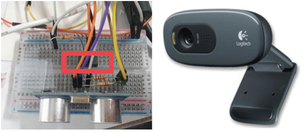
회로[첨부 1]에 연결된 스위치가 ON 일 때, 차선 변경 알고리즘이 실행되면서 카메라(Logitech사의 960-001063 – Webcam, HD Pro, 1280 x 720p Resolution, 3MP, Built In Microphone, [첨부 2])가 동작하게 된다.
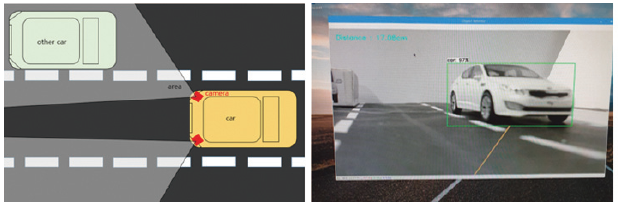
[첨부 3]운전자 차량의 뒷면에서 대각선 양쪽 끝에 카메라를 장착한다는 가정에 하에 카메라에 나타나는 화면[첨부 4]은 카메라가 가리키는 곳의 도로 상황을 보여준다. 여기서 카메라는 운전자의 시야를 대신할 뿐 아니라 동시에 Raspberry Pi의 OpenCV의 영상처리를 통해 물체를 인식해 운전자의 차량과 가장 가까운 차량을 인식하는 역할을 한다.3.1.2. 초음파 동작 및 특징
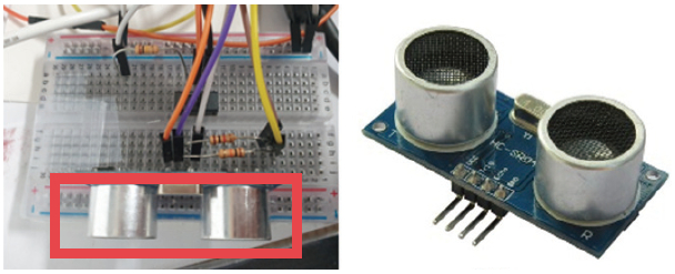
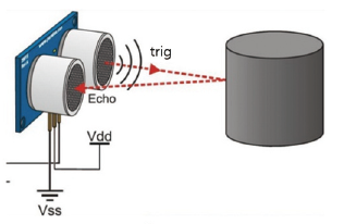
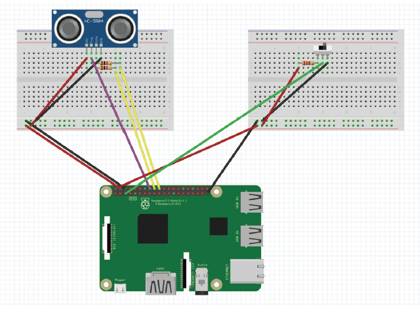
회로[첨부 5]에 연결된 스위치가 ON 일 때, 같이 연결되어 있던 초음파(HC-SR04, [첨부 6])가 동작하게 된다. HC-SR04 초음파 센서는 4가지 핀이 있으며, 순서대로 VCC핀, Trig핀, Echo핀, GND 핀을 가지고 있다.
여기서 초음파 센서의 동작을 살펴보면, Trig핀에 High signal이 들어오면 초음파를 전송하고 전송된 초음파가 사물에 반사되어 돌아오면 High signal에서 Low signal로 바뀐다. High상태에서 Low상태로 바뀐 시간을 이용하여 거리를 측정할 수 있다. 거리 계산 공식은 “거리 = 시간 x 초음파의 속력”이며, 초음파의 속력은 공기 중에서 340m/s로 이동하기에 식에 340m/s를 대입하여 계산하면 된다. 참고로 시간은 왕복시간으로 측정이 되기 때문에 2를 나누어 주며, 마무리로 단위까지 맞춰주어 간단하게 거리를 구할 수 있다.
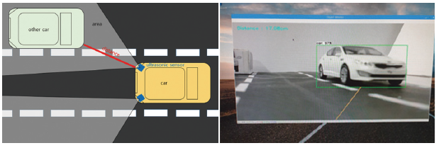
이러한 초음파를 활용하여 [첨부 8]운전자 차량의 뒷면에서 대각선 양쪽 끝에 초음파 센서를 장착한다는 가정에 하에 초음파 센서는 운전자 차량과 변경하고자 하는 차선의 뒷 차량과의 거리를 측정할 수 있게 된다. 더 나아가 초음파 센서가 측정한 거리를 라즈베리에서 받아 처리함으로써 차선 변경 시 안전 정도를 운전자가 보는 모니터에 영상처리를 통해 간단하게 인지할 수 있게 해주는 역할을 제공한다. [첨부9]같은 경우 위험(빨강색) – 주의(주황색) – 안전(초록색) 중 주의 단계로 주황색으로 위험 정도를 표시하고 있는 것을 볼 수 있다.
3.1.3. 차선 변경 동작 및 특징
3.2. 전체 시스템 구성
3.2.1. 하드웨어 구성
· Raspberry Pi
· 960-001063 – Webcam, HD Pro, 1280 x 720p Resolution, 3MP, Built In Microphone
· HC-SR04
· Bread Board
· 저항 1K 2개, 저항 2K1개
· Slide switch
· Google Coral USB Accelerator
· MM,MF 타입 점퍼선
3.2.2. 소프트웨어 구성
· OpenCV 영상인식 source
· Ultrasonic sensor source
· Switch On/Off process source
3.2.3. 주요 동작 및 특징
· 영상처리를 통한 뒷 차량 인식
· 초음파센서를 통한 뒷 차량과의 거리 계산
· 스위치를 통한 깜박이 구현
· 영상처리를 통한 차선 변경 안전도 표시
3.2.4. 회로 구성
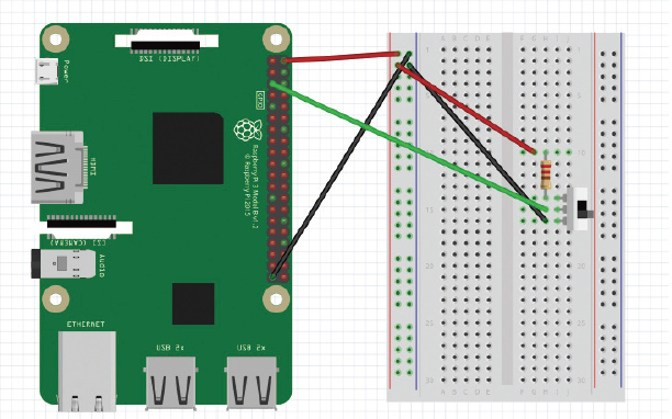
Raspberry Pi 2Pin = Register 1K pin = Switch first pin
Raspberry Pi 4pin = ultrasonic sensor Vcc pin
Raspberry Pi 5pin = Switch second pin
Raspberry Pi 6pin = ultrasonic sensor GND pin
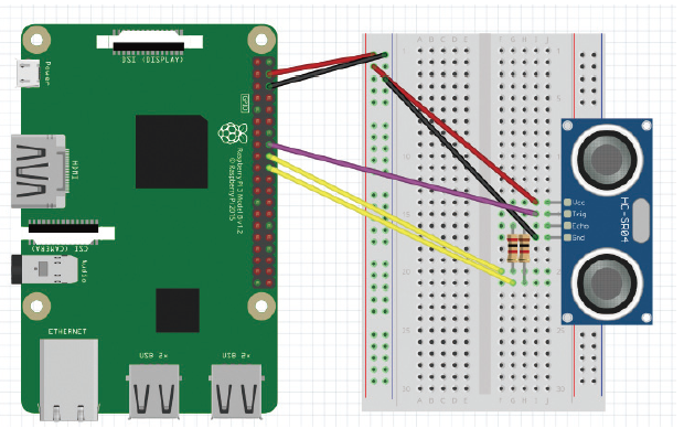
Raspberry Pi 16pin = ultrasonic sensor Trig pin
Raspberry Pi 18pin = Register 2K pin = ultrasonic sensor Echo pin
Raspberry Pi 20pin = Register 1K pin = ultrasonic sensor Echo pin
Raspberry Pi 39pin = Switch third pin
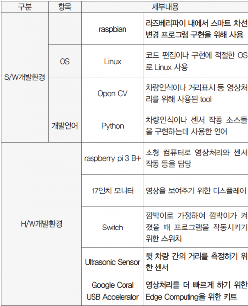
3.3. 개발 환경(개발 언어, Tool, 사용 시스템 등)
4. 단계별 제작 과정
4.1. 라즈베리 파이
4.1.1. 차량인식을 위한 영상처리 구현
구현하고자 하는 프로그램의 핵심은 차량인식이다. 차선 변경 시, 해당 도로에서 운전자 차량을 기준으로 대각선 뒤에 있는 차량과의 거리를 시각적인 정보로 운전자에게 표현하기 위해서는 차량을 인식하는 것이 가장 우선이다. 영상 처리를 위한 환경으로 라즈베리에 tensorflow를 설치하였고 코딩을 위해 Open CV tool도 설치하였다. 언어는 Python을 사용하였다. 여러 가지 환경과 쉘 스크립트를 사용하기 위해 https://github.com/EdjeElectronics/ TensorFlow-Lite-Object-Detection-on-Android-and-Raspberry-Pi.git 저장소를 사용했고, 감지 모델은 tensorflow 홈페이지에서 제공하는 모델을 기반으로 사용했다.
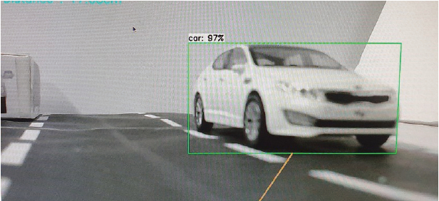
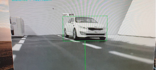
다음은 테스트의 한 부분으로 다음과 같이 차량을 인식하여 차량을 사각형 틀 안에 포함하는 것을 볼 수 있다.
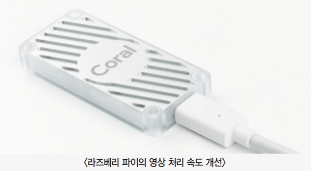
라즈베리 파이 상에서 영상처리를 하였는데 영상 처리가 워낙 많은 연산을 필요로 하다보니 속도가 늦은 단점이 있었다. 이를 개선하기 위해 Google Coral USB Accelerator라는 Edge TPU를 사용하여 속도를 높여주었다.
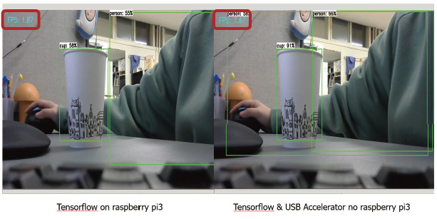
성능을 테스트해보기 위해 FPS를 측정해 보았다. Google Coral USB Accelerator 장착했을 때 FPS가 4배 가까이 증가하는 것을 확인할 수 있었고, 좀 더 빠른 영상처리를 할 수 있었다. 하지만 실시간으로 이용하기에는 조금 부족한 면이 있었지만 이는 라즈베리보다 좀 더 성능이 좋은 소형 컴퓨터를 이용하면 해결될 것이라고 본다. 예들 들면 Nvidia사의 Jetson Nano Board나 Raspberry pi 4 등이다.
4.1.2. 운전자가 쉽게 차량까지의 거리를 인식할 수 있게 시각화하기
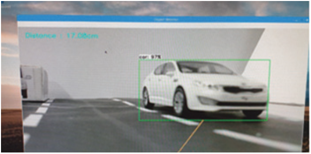
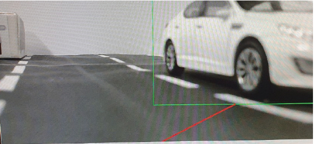
운전자 차량을 기준으로 변경하고자 하는 차선의 차량까지의 거리는 cm단위로 초음파 센서를 통해 측정하였으며, 좌측 상단에 “Distance : ”로 출력형태를 갖는다. Python OpenCV를 통해 거리를 선으로 표시하며 색(빨간색, 주황색, 초록색)을 통해 상황에 따라 구별할 수 있도록 한다.
운전자 차량까지의 거리를 인식할 수 있는 구체적인 설명으로는 거리측정을 위한 초음파 센서를 연결하고, 초음파 센서에서 반환값을 받아온다. 여기서 받아온 값은 구하고자 하는 거리가 되며 cm단위(테스트를 모형에서 실시했기 때문에 거리를 cm로 조정)를 갖는다. 여기서 운전자 차량과 변경하고자 하는 차선의 차량과의 거리는 선으로 표시한다. 이 선은 거리에 따라서 색을 다르게 표현하는데, 만약 거리가 16cm이하라면, 해당 선을 빨간색으로 하여 차선변경이 불가능하다고 알려주고, 16cm~ 20cm 사이면 해당 선은 주황색으로 차선 변경 시 주의해야 한다고 알려주며, 20cm이상이면 해당 선은 초록색으로 차선 변경을 하여도 안전하다고 표시하도록 구성하였다.
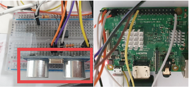
테스트는 다음과 같이 진행하였다. 카메라는 운전자 차량의 후면에 부착하였다고 가정한 상태에서 빨간색 차량이 운전자의 차량이며 운전자가 좌측 방향 지시등을 켰을 때, 운전자 차량을 기준으로 좌측 도로 상황을 비추게 된다. 카메라는 OpenCV를 통해 차량을 인식하는 동시에 앞서 말한 시각화 과정으로 차선 변경 가능 여부를 선과 색으로 운전자에게 알려준다. 다음의 테스트에서는 라즈베리 파이 모델 3 2015버전을 사용하였고 초음파 센서의 모델명은 HC-SR04, 카메라는 Logitech사의 960-001063 – Webcam, HD Pro, 1280 x 720p Resolution, 3MP, Built In Microphone을 사용하였다. 실제 차량을 사용할 수 없어 차량 모델을 제작하여 테스트를 진행하였다.
회로 사진 및 라즈베리파이 pin 연결
초음파 센서 회로도
4.1.3. 스위치를 이용한 방향 지시등 구현
운전자가 방향 지시등을 켰을 때 다음 프로그램이 실행되므로 슬라이드 스위치를 차량의 방향 지시등으로 가정하여 구현하였다. 슬라이드 스위치가 ON일 때, 프로그램을 시작하거나 프로그램이 지속적으로 실행하도록 한다. 슬라이드 스위치가 OFF일 때, 프로그램을 종료하도록 구성하였다. 실험을 진행 할 때, 일반적인 택트 스위치 같은 경우 직접 스위치를 계속해서 누르고 있어야 ON으로 인식을 하는 번거로움을 가져왔다. 따라서 슬라이드 스위치를 이용하여 실제 차량의 방향지시등의 점멸을 표현하였다. 슬라이드 스위치의 작동 실험은 시연 동영상을 통해 볼 수 있다.
회로 사진
회로도
4.1.4. 주요 소스 코드
import RPi.GPIO as GPIO
from time import sleep
import os
import argparse
import cv2
import numpy as np
import sys
import time
from threading import Thread
import importlib.util
import signal
left_switch = 3 #Switch assumed as signal light
#GPIO Setting
GPIO.setmode(GPIO.BCM)
GPIO.setwarnings(False)
GPIO.setup(left_switch,GPIO.IN,GPIO.PUD_UP)
GPIO.setup(right_switch,GPIO.IN,GPIO.PUD_UP)
def distanceInCm(duration): #Function that returns duration as distance in cm
return (duration/2)/29.1
def print_distance(distance): #A function that sets the distanceMsg differently depending on the distance value.
if distance == 0:
distanceMsg = ‘Distance : out of range \r’
else:
distanceMsg = ‘Distance : ‘+str(distance)+’cm’+’ \r’
return distanceMsg
#Set pin number of ultrasonic sensor
TRIG = 23 #TRIG Numbering
ECHO = 24 #ECHO Numbering
MAX_DISTANCE_CM = 300
MAX_DURATION_TIMEOUT = (MAX_DISTANCE_CM * 2 * 29.1)
GPIO.setmode(GPIO.BCM)
GPIO.setup(TRIG, GPIO.OUT) #TRIG Ultrasonic Signal Transmission Pin Designation and Specify Output
GPIO.setup(ECHO, GPIO.IN) #Specify ECHO Ultrasonic Signal Receiving Pin and Specify Output
#Thread to manage webcam
class VideoStream:
“”"Camera object that controls video streaming from the Picamera”"”
def __init__(self, resolution=(640,480), framerate=30):
self.stream = cv2.VideoCapture(0) #Trun on the camera
ret = self.stream.set(cv2.CAP_PROP_FOURCC, cv2.VideoWriter_fourcc(*’MJPG’))
#frame size init
ret = self.stream.set(3, resolution[0])
ret = self.stream.set(4, resolution[1])
# Read first frame from the stream
(self.grabbed, self.frame) = self.stream.read()
# Variable to control when the camera is stopped
self.stopped = False
def start(self): # Start the thread that reads frames from the video stream
Thread(target=self.update,args=()).start()
return self
def update(self): #Keep looping indefinitely until the thread is stopped
while True:
#If the camera is stopped, stop the thread
if self.stopped:
#Close camera resources
self.stream.release()
return
#Otherwise, grab the next frame from the stream
(self.grabbed, self.frame) = self.stream.read()
def read(self): #Return the most recent frame
return self.frame
def stop(self): #Indicate that the camera and thread should be stopped
self.stopped = True
#Define and parse input arguments
parser = argparse.ArgumentParser()
parser.add_argument(‘–modeldir’, help=’Folder the .tflite file is located in’, required=True)
parser.add_argument(‘–edgetpu’, help=’Use Coral Edge TPU Accelerator to speed up detection’, action=’store_true’)
args = parser.parse_args()
MODEL_NAME = args.modeldir
GRAPH_NAME = args.graph
LABELMAP_NAME = args.labels
min_conf_threshold = float(args.threshold)
resW, resH = args.resolution.split(‘x’)
imW, imH = int(resW), int(resH)
use_TPU = args.edgetpu
#Import TensorFlow libraries
#If tensorflow is not installed, import interpreter from tflite_runtime, else import from regular tensorflow
#If using Coral Edge TPU, import the load_delegate library
pkg = importlib.util.find_spec(‘tensorflow’)
if pkg is None:
from tflite_runtime.interpreter import Interpreter
if use_TPU:
from tflite_runtime.interpreter import load_delegate
else:
from tensorflow.lite.python.interpreter import Interpreter
if use_TPU:
from tensorflow.lite.python.interpreter import load_delegate
#If using Edge TPU, assign filename for Edge TPU model
if use_TPU: #If user has specified the name of the .tflite file, use that name, otherwise use default ‘edgetpu.tflite’
if (GRAPH_NAME == ‘detect.tflite’):
GRAPH_NAME = ‘edgetpu.tflite’
#Get path to current working directory
CWD_PATH = os.getcwd()
#Path to .tflite file, which contains the model that is used for object detection
PATH_TO_CKPT = os.path.join(CWD_PATH,MODEL_NAME,GRAPH_NAME)
#Path to label map file
PATH_TO_LABELS = os.path.join(CWD_PATH,MODEL_NAME,LABELMAP_NAME)
#Load the label map
with open(PATH_TO_LABELS, ‘r’) as f:
labels = [line.strip() for line in f.readlines()]
#Have to do a weird fix for label map if using the COCO “starter model” from
#https://www.tensorflow.org/lite/models/object_detection/overview
#First label is ‘???’, which has to be removed.
if labels[0] == ‘???’:
del(labels[0])
#Load the Tensorflow Lite model.
#If using Edge TPU, use special load_delegate argument
if use_TPU:
interpreter = Interpreter(model_path=PATH_TO_CKPT,
experimental_delegates=[load_delegate('libedgetpu.so.1.0')])
print(PATH_TO_CKPT)
else:
interpreter = Interpreter(model_path=PATH_TO_CKPT)
interpreter.allocate_tensors()
#Get model details
input_details = interpreter.get_input_details()
output_details = interpreter.get_output_details()
height = input_details[0]['shape'][1]
width = input_details[0]['shape'][2]
floating_model = (input_details[0]['dtype'] == np.float32)
input_mean = 127.5
input_std = 127.5
#Initialize frame rate calculation
frame_rate_calc = 1
freq = cv2.getTickFrequency()
#Initialize video stream
videostream = VideoStream(resolution=(imW,imH),framerate=30).start()
time.sleep(1)
#for frame1 in camera.capture_continuous(rawCapture, format=”bgr”,use_video_port=True):
while True:
if GPIO.input(left_switch) == 1: #Start timer (for calculating frame rate)
t1 = cv2.getTickCount()
#Grab frame from video stream
frame1 = videostream.read()
#Acquire frame and resize to expected shape [1xHxWx3]
frame = frame1.copy()
frame_rgb = cv2.cvtColor(frame, cv2.COLOR_BGR2RGB)
frame_resized = cv2.resize(frame_rgb, (width, height))
input_data = np.expand_dims(frame_resized, axis=0)
#Normalize pixel values if using a floating model (i.e. if model is non-quantized)
if floating_model:
input_data = (np.float32(input_data) – input_mean) / input_std
#Perform the actual detection by running the model with the image as input
interpreter.set_tensor(input_details[0]['index'],input_data)
interpreter.invoke()
#Retrieve detection results
boxes = interpreter.get_tensor(output_details[0]['index'])[0] #Bounding box coordinates of detected objects
classes = interpreter.get_tensor(output_details[1]['index'])[0] #Class index of detected objects
scores = interpreter.get_tensor(output_details[2]['index'])[0] #Confidence of detected objects
#num = interpreter.get_tensor(output_details[3]['index'])[0] #Total number of detected objects (inaccurate and not needed)
pulse_start=0
pulse_end=0
GPIO.output(TRIG, False) #Keep the trigger pin off.
time.sleep(2)
GPIO.output(TRIG, True) #Exits 10us pulse.
time.sleep(0.00001) #At Python, this pulse will be almost 100 us.
GPIO.output(TRIG, False)
timeout = time.time()
while GPIO.input(ECHO) == 0:
pulse_start = time.time() #Set the start time when the echo pin is turned on.
if ((pulse_start – timeout)*1000000) >= MAX_DURATION_TIMEOUT:
fail = True
break
timeout = time.time()
while GPIO.input(ECHO) == 1:
pulse_end = time.time() #Set the reflector receiving time when the echo pin is turned off.
if ((pulse_end – pulse_start)*1000000) >= MAX_DURATION_TIMEOUT:
print_distance(0)
fail = True
break
pulse_duration = (pulse_end – pulse_start) * 1000000
pulse_duration=pulse_end-pulse_start #Calculate pulse length
distance = distanceInCm(pulse_duration)
distance=(pulse_duration*34000.0)/2 #The duration is divided in half.
distance = round(distance, 2)
MSG=print_distance(distance)
#Loop over all detections and draw detection box if confidence is above minimum threshold
for i in range(len(scores)):
if ((scores[i] > min_conf_threshold) and (scores[i] <= 1.0)):
#Get bounding box coordinates and draw box
#Interpreter can return coordinates that are outside of image dimensions, need to force them to be within image using max() and min()
ymin = int(max(1,(boxes[i][0] * imH)))
xmin = int(max(1,(boxes[i][1] * imW)))
ymax = int(min(imH,(boxes[i][2] * imH)))
xmax = int(min(imW,(boxes[i][3] * imW)))
cv2.rectangle(frame, (xmin, ymin), (xmax, ymax), (10, 255, 0), 2)
a=(xmax-xmin)/2
b = int(a)
if distance < 16:
frame = cv2.line(frame, (650, 720), (xmin+b, ymax), (0, 0, 255), 3)
elif distance >=16 and distance < 20:
frame = cv2.line(frame, (650, 720), (xmin+b, ymax), (0, 150, 255), 3)
else:
frame = cv2.line(frame, (650, 720), (xmin+b, ymax), (0, 255, 0), 3)
#Draw label
object_name = labels[int(classes[i])] #Look up object name from “labels” array using class index
label = ‘%s: %d%%’ % (object_name, int(scores[i]*100)) #Example: ‘person: 72%’
labelSize, baseLine = cv2.getTextSize(label, cv2.FONT_HERSHEY_SIMPLEX, 0.7, 2) #Get font size
label_ymin = max(ymin, labelSize[1] + 10) #Make sure not to draw label too close to top of window
cv2.rectangle(frame, (xmin, label_ymin-labelSize[1]-10), (xmin+labelSize[0], label_ymin+baseLine-10), (255, 255, 255), cv2.FILLED) #Draw white box to put label text in
cv2.putText(frame, label, (xmin, label_ymin-7), cv2.FONT_HERSHEY_SIMPLEX, 0.7, (0, 0, 0), 2) #Draw label text
#Draw distance in corner of frame
cv2.putText(frame, MSG,(30,50),cv2.FONT_HERSHEY_SIMPLEX,1,(255,255,0),2,cv2.LINE_AA)
#All the results have been drawn on the frame, so it’s time to display it.
cv2.imshow(‘Object detector’, frame)
#Calculate framerate
t2 = cv2.getTickCount()
time1 = (t2-t1)/freq
frame_rate_calc= 1/time1
#Press ‘q’ to quit
if cv2.waitKey(1) == ord(‘q’):
break
else: #Exit program if switch off
break
#Clean up
GPIO.cleanup()
cv2.destroyAllWindows()
videostream.stop()
5. 추가할 수 있는 기능
우리는 도로 모형을 제작하여 실험을 진행하였지만 실제 도로 상황에서는 많은 변수가 존재할 수 있다. 우리가 생각한 변수 중의 하나는 바로 ‘속도’이다. 뒷 차량이 어느 정도 속도로 오는지 알 수 없기 때문에 우리는 거리를 통하여 속도를 계산해 운전자의 모니터에 거리 정보를 나타낼 때 변수가 되는 속도를 반영하여 나타내는 것이다. 우리는 실제로 실험을 할 수 없어 이 부분의 구현은 하지 않았지만 우리가 만든 프로그램을 실제 차량에 이용한다면 이 부분도 고려하면 좋을 것 같다. 아니면 초음파를 받아 오는 시간 간격을 좀 더 줄여도 속도라는 변수를 어느 정도 해결할 수 있을 것 같다.
6. 참고문헌
· https://github.com/EdjeElectronics/TensorFlow-Lite-Object-Detection-on-Android-and-Raspberry-Pi/blob/master/Raspberry_Pi_Guide.md
· https://www.tensorflow.org
· https://blog.naver.com/ljy9378/221438192568
· https://www.diymaker.net/111
· https://www.diymaker.net/111
· https://make.e4ds.com/make/learn_guide_view.asp?idx=73

